Product Overview
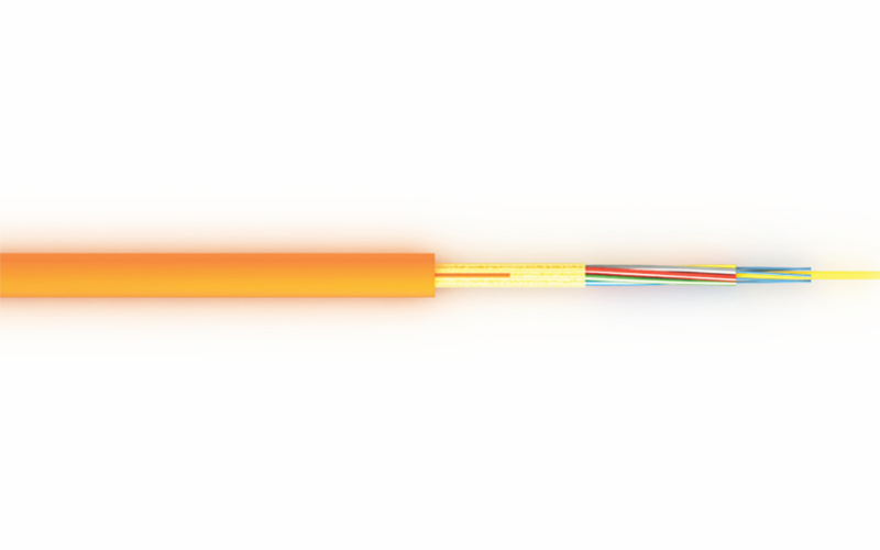
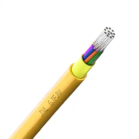
GJFJV indoor distribution fiber optic cable combines multiple color-coded tight-buffered fibers inside a compact common jacket. Aramid yarn provides tensile reinforcement without introducing metal components. Available in single-mode and multimode configurations, the cable is designed for building backbones, equipment rooms, conduits and indoor fiber distribution systems.
Product Overview
Unlike breakout cable, GJFJV distribution cable does not place every fiber inside a separate simplex subunit. The color-coded tight-buffered fibers are grouped together with aramid yarn and protected by one common outer jacket.
This construction keeps the overall diameter and weight lower than a breakout cable of the same fiber count. It is a practical choice when several fibers need to pass through the same conduit or cable tray and will be terminated inside a patch panel, distribution frame or termination box.
The 900 μm tight buffers provide better handling during stripping, routing and splicing than bare 250 μm fibers. For connectorized installation, a breakout kit may be used where additional protection is required between the stripped cable and individual connectors.
Cable Construction
The standard construction includes:
Color-coded 900 μm tight-buffered fibers
Aramid yarn strength member
Optional binding or wrapping layer
PVC or LSZH outer jacket
No steel armor or gel filling is used in the standard indoor distribution construction.
Key Features
Compact multi-fiber indoor cable
Common outer jacket reduces diameter and weight
2–24 fiber configurations
Color-coded tight buffers simplify identification
Aramid yarn provides tensile reinforcement
Metal-free construction
Easy stripping and routing
PVC and LSZH jacket options
Single-mode and multimode fiber options
Suitable for trays, conduits and vertical indoor routes
Custom jacket color, printing and delivery length
Distribution Cable vs Breakout Cable
| Selection point | GJFJV distribution cable | GJBFJV breakout cable |
|---|---|---|
| Fiber protection | Tight buffer and common jacket | Individually reinforced subunit for every fiber |
| Cable diameter | Smaller | Larger |
| Cable weight | Lower | Higher |
| Direct connector termination | May require a fan-out or breakout kit | Individual subunits can be terminated directly |
| Typical installation | Patch panels, conduits and building distribution | Direct equipment runs and rugged indoor links |
| Cost | Usually lower | Usually higher |
Choose distribution cable when space, weight and cable density matter. Choose breakout cable when individual fibers must leave the main cable and continue as independently protected units.
Available Fiber Options
G.652D single-mode
G.657A1 bend-insensitive single-mode
G.657A2 bend-insensitive single-mode
OM1 62.5/125 μm multimode
OM2 50/125 μm multimode
OM3 laser-optimized multimode
OM4 laser-optimized multimode
OM5 wideband multimode
These options should remain on one product page. Separate pages for every fiber grade would create substantially similar content.
Typical Mechanical Specifications
| Item | Typical specification |
|---|---|
| Fiber count | 2, 4, 6, 8, 12 or 24 |
| Tight-buffer diameter | 900 μm |
| Strength member | Aramid yarn |
| Jacket material | PVC or LSZH |
| Long-term tensile load | 200 N |
| Short-term tensile load | 660 N |
| Long-term crush load | 300 N/100 mm |
| Short-term crush load | 1000 N/100 mm |
| Static bending radius | 10 × cable diameter |
| Dynamic bending radius | 20 × cable diameter |
| Operating temperature | −20°C to +60°C |
| Installation environment | Indoor |
Typical Dimensions
| Fiber count | Nominal cable diameter | Approximate cable weight |
|---|---|---|
| 4 fibers | Subject to construction | Subject to construction |
| 6 fibers | 5.1 mm | 24 kg/km |
| 8 fibers | 5.6 mm | 26 kg/km |
| 12 fibers | 6.2 mm | 35 kg/km |
| 24 fibers | 8.0 mm | 58 kg/km |
These are reference values for preliminary selection. Actual diameter and weight must be confirmed according to the fiber type, buffer material, jacket thickness and flame-retardant requirement.
Applications
Indoor building backbone cabling
Telecom equipment rooms
Data center distribution
Fiber optic patch panels
Optical distribution frames
Cable trays and conduits
Security and surveillance networks
Campus communication systems
Voice, video and data transmission
Indoor links between communication rooms
Installation Considerations
The minimum bending radius should be maintained during pulling and final placement. Excessive tie pressure can deform the jacket and transfer stress to the fibers, so hook-and-loop fasteners or correctly sized cable supports are preferred.
When individual fibers extend beyond the cable jacket, protect the transition with a suitable breakout kit, splice tray or enclosure. The cable is intended for indoor use unless an indoor/outdoor-rated construction is specifically ordered.
Ordering Information
Please specify:
Fiber count
Fiber type
PVC or LSZH outer jacket
Jacket color
Required fire-performance level
Cable diameter limitation
Installation environment
Delivery length
Cable printing
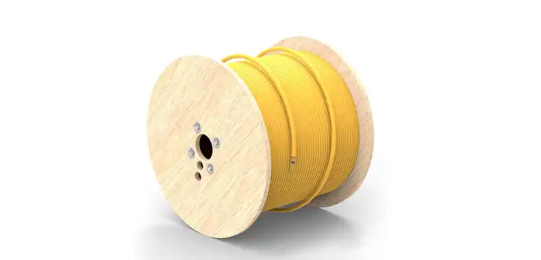
Drum or coil packaging
Required test documentation
For installations that need individually protected subunits, see the GJBFJV breakout fiber optic cable. For completed terminations, matching fiber optic pigtails can be supplied according to the required fiber and connector type.
Frequently Asked Questions
What is GJFJV distribution cable used for?
It is used to route several tight-buffered fibers through indoor trays, conduits, equipment rooms and building backbone systems using one compact outer jacket.
Does every fiber have an individual jacket?
Each fiber has a colored tight buffer, but it does not have the complete aramid reinforcement and subunit jacket found in a breakout cable.
Can connectors be installed directly?
Direct termination is possible in some configurations, but a breakout or fan-out kit may be preferred where individual fibers need additional protection.
Is the cable suitable for outdoor installation?
The standard GJFJV construction is intended for indoor use. Outdoor or indoor/outdoor cable should be selected when moisture, sunlight or significant temperature exposure is expected.
Which fiber count should be selected?
The choice depends on the number of active links, spare-fiber requirements and future expansion. Common configurations include 4, 6, 8, 12 and 24 fibers.
Can different fiber types be combined in one cable?
Hybrid fiber arrangements may be manufactured when confirmed during engineering review. The required fiber quantities, color sequence and test criteria must be stated in the order.