Specifications, compatibility and ordering information
24-Core Sliding Rack-Mount Fiber Optic Termination Box
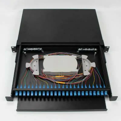
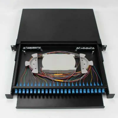
This 24-Core Sliding Rack-Mount Fiber Optic Termination Box provides an organized termination point for incoming optical cables inside telecom rooms, equipment racks and indoor fiber distribution systems. The sliding drawer gives technicians access to the internal splice and routing area without removing the complete enclosure from the rack.
The internal layout combines fiber splicing, pigtail routing, adapter termination and excess-fiber management, making the box suitable for links that need accessible connectorized termination at the rack level.
Key Features
24-core fiber termination capacity
Sliding drawer structure for service access
Rack-mount installation
Integrated splice and fiber routing area
Front adapter panel for connectorized termination
Supports common fiber adapter configurations
Suitable for telecom rooms, equipment racks and indoor distribution points
Specifications
| Parameter | Specification |
|---|---|
| Product Type | Rack-Mount Fiber Optic Termination Box |
| Fiber Capacity | 24 Cores |
| Structure | Sliding Drawer |
| Installation | Rack Mount |
| Fiber Splicing | Supported |
| Pigtail Management | Supported |
| Adapter Interface | Configured According to Project Requirement |
| Application Environment | Indoor |
| Housing | Metal Enclosure |
Why Use a Sliding Termination Box?
The sliding structure allows the internal splice tray, pigtails and fiber routing area to be accessed from the front of the rack. This is useful in equipment rooms where multiple fiber links need to remain serviceable after installation.
Compared with an outdoor FTTH termination box, this product is intended for rack-based indoor termination rather than subscriber drop distribution. The main task is to bring incoming fibers into an organized splice and connector interface that can be patched to active equipment or other fiber routes.
Typical Applications
Telecommunication equipment rooms
Indoor fiber distribution racks
Building fiber backbone termination
Equipment-side fiber patching
Enterprise network rooms
Fiber testing and maintenance points
Compatible fiber adapters and fiber pigtails can be selected according to the connector interface required by the installed network.
Adapter and Pigtail Configuration
The front termination interface should be selected according to the installed connector system. SC, LC, FC or ST configurations can be considered depending on the equipment, patch cord and existing fiber infrastructure.
Connector polish, fiber mode and pigtail type should match the optical link rather than being selected from the enclosure alone.
Details to Confirm Before Ordering
Confirm the required fiber capacity, rack installation format, adapter type, connector polish, single-mode or multimode fiber, splice configuration and quantity before quotation. For replacement projects, a photo of the existing rack and adapter panel can help confirm the required layout.