Product Overview
An optical fiber attenuator is a passive optical device whose core function is to artificially and precisely reduce the power of optical signals in an optical fiber link.
You can think of it as an "optical signal conditioning valve" or "faucet" in the optical signal transmission process. In optical fiber communication, higher optical power is not always better. If the optical signal is too strong, it will overload the receiving equipment (such as optical modules), leading to nonlinear distortion and increasing the bit error rate. The task of the optical fiber attenuator is to precisely attenuate excessive optical power to within the range of normal equipment operation, thereby ensuring the stability and reliability of the entire link transmission.
Working Principle and Types
Optical fiber attenuators mainly achieve optical signal attenuation in the following ways:
* **Air Gap Attenuation:** By creating a precisely controlled tiny air gap between the fiber end faces, the beam diverges, thereby reducing the optical power coupled to the receiving fiber. This method has a simple structure, but the attenuation value is easily affected by end face contamination.
* **Thin Film Attenuation:** A thin film with specific absorption or reflection properties is inserted into the optical path to achieve attenuation by absorbing or reflecting part of the light energy. This method has stable performance and is less dependent on polarization and wavelength.
Offset attenuation: The cores of two optical fibers are precisely offset laterally to prevent some light from coupling into the receiving fiber. This method has a simple structure, but the attenuation value is sensitive to wavelength.
Ion-doped fiber attenuation: Special ions (such as cobalt or chromium) are doped into the fiber, utilizing their light absorption characteristics to achieve attenuation. This method has stable performance, but the cost is relatively high.
Main Classifications: Fiber optic attenuators can be classified according to various sizes to meet different application requirements.
Based on whether the attenuation value is adjustable:
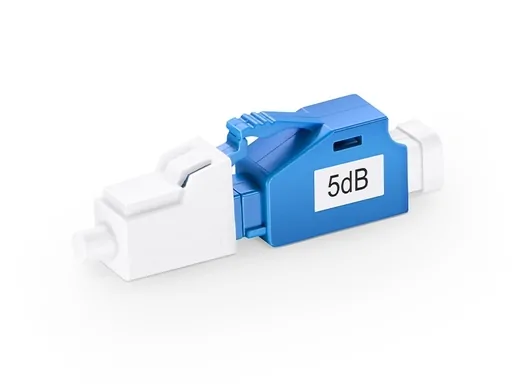
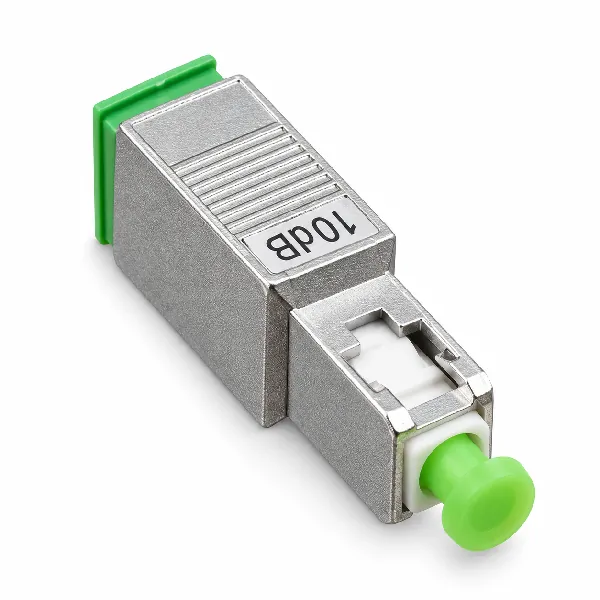
Fiber optic attenuators: Provide a fixed attenuation value (e.g., 1dB, 3dB, 5dB, 10dB, etc.), offering advantages such as high precision, low cost, and stable performance, and are the most widely used type in networks.
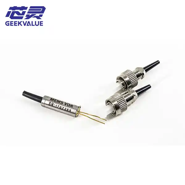
Variable attenuators: Allow continuous adjustment of the attenuation value within a certain range (e.g., 0.5dB~30dB). Variable attenuators are divided into manual adjustment and electronically controlled adjustment (EVOA). The latter is often used in automatic gain control in dense wavelength division multiplexing (DWDM) systems.
Based on connector type: Primarily compatible with common interface types such as SC, LC, FC, and ST. By connection method and form:
* **Male/Female Plug Type:** Similar to an adapter, one end is a male connector (plug), and the other end is a female connector (socket). It can be directly inserted into a device port or connected between patch cords, providing the most convenient application method.
* **Direct Plug/Fiber Type:** The attenuator itself is a fiber optic patch cord with a connector, typically used for permanent connections between panels and devices.
* **Adapter Type:** Similar in appearance to a standard fiber optic adapter (flange), it contains an attenuator for connecting two fiber optic patch cords.
By end face polishing type: Usually corresponds to the connector end face type, such as PC, UPC (return loss ≥50dB), and APC (return loss ≥60dB).
Key Performance Indicators
The core parameters for evaluating fiber optic attenuator performance include:
* **Attenuation:** The core parameter of the attenuator, representing the degree of optical power attenuation. Commonly fixed values are 1~20dB, with a wider variable range. Accuracy is an important performance indicator.
* **Return Loss (RL):** The energy reflected back to the light source. Higher values are better; typically, UPC ≥ 50dB and APC ≥ 60dB are required.
Operating wavelength range: Must match the system's operating wavelength. Typical broadband attenuators cover a wavelength range of 1260~1650nm.
Polarization-dependent loss (PDL): Loss caused by changes in the polarization state of the optical signal; typically ≤0.15dB is required.
Temperature stability: The degree of attenuation drift under different temperature conditions, reflecting its reliability in complex environments.
Main Application Scenarios
Fiber optic attenuators are common tools for fiber optic network maintenance and optimization, widely used in the following scenarios:
* **Optical Power Adjustment:** In PON (Passive Optical Network) systems, ensuring consistent optical power received by users at different distances.
* **Solving Overpower Issues:** In short-distance transmission links, preventing receiver saturation caused by strong signals.
* **Equipment Equalization and Gain Slope Control:** In DWDM (Dense Wavelength Division Multiplexing) systems, using variable attenuators to precisely adjust the power of each channel to achieve system equalization.
* **Testing and Measurement:** Used in laboratories or production lines to simulate fiber optic link loss and test equipment performance.
* **Telecommunications, CATV, and Data Centers:** Widely used for the maintenance and optimization of various fiber optic networks.
How to Choose and Use?
When choosing a suitable attenuator, consider the following:
* **Determine the Attenuation Value:** First, calculate the difference between the actual received optical power of the link and the equipment's receiving sensitivity, then select a standard attenuation value slightly larger than this difference.
* **Choose the Appropriate Type:**
If the attenuation value is fixed, choose a fixed attenuator.
If debugging or power equalization is required, choose a variable attenuator.
Connector and Endface Matching: Ensure the interface type (SC/LC/FC, etc.) and endface type (PC/UPC/APC) are completely matched. Mixing PC/UPC and APC will damage the connector.
Selection Recommendation: For permanent links, it is recommended to use in-line or high return-loss male-female type.
For testing or temporary scenarios, male-female type is the most convenient.
Safety Reminder: When operating variable attenuators or using in-line attenuators, never look directly at the connector port, as invisible laser radiation may still exist even after attenuation.
Summary: In conclusion, although fiber optic attenuators have a simple structure, they are a key guarantee for ensuring the performance and reliability of fiber optic links. By precisely controlling optical power, they effectively prevent receiver overload and are an indispensable tool for network engineers when maintaining and optimizing fiber optic networks. Choosing the correct attenuator type and parameters is crucial for building a stable and efficient communication system.