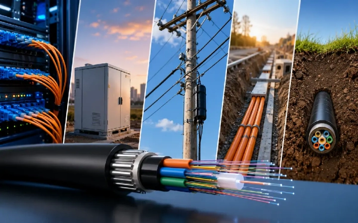
Discover how optical transceivers work in data centers—from 100G SFP+ to 800G OSFP. Compare form factors, reach, and deployment across spine-and-leaf fabrics and AI networks.
Optical transceivers are compact, pluggable devices that convert electrical signals into pulses of light—and back again—enabling the vast majority of high-speed data movement inside modern data centers. Every search query, AI training run, cloud workload, and video stream that travels between servers relies on these modules to cross the gap between computing chips and fiber optic cabling. Without them, the bandwidth, distance, and energy efficiency demands of contemporary computing simply could not be met.
Understanding how optical transceivers function, where they fit within data center architectures, and why their role continues to expand is essential for anyone involved in building, operating, or planning digital infrastructure.
What an Optical Transceiver Actually Does
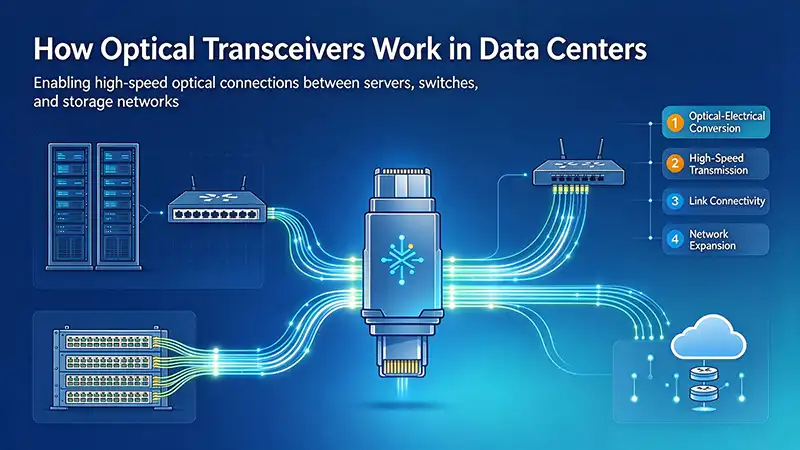
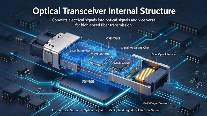
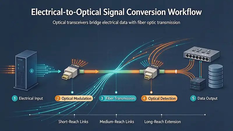
At its core, an optical transceiver serves as a translator. On one side sits an electrical interface—a standardized port on a switch, router, or server network card. On the other side is an optical interface designed to mate with fiber optic cabling. The transceiver's internal circuitry performs two essential conversions.
When data leaves a switch chip, it arrives at the transceiver as high-speed electrical signals. A laser or vertical-cavity surface-emitting laser (VCSEL) inside the module modulates these electrical signals into light pulses. Those pulses travel through the fiber, sometimes for meters, sometimes for kilometers. At the receiving end, a photodetector captures the incoming light and converts it back into electrical signals that the destination device can process.
The word "transceiver" itself reflects this dual nature: transmitter plus receiver. A single module handles both directions of a bidirectional link, often simultaneously across multiple parallel lanes.
Form factor standards dictate the physical dimensions and electrical pin layouts of these modules. The most widely deployed families include:
SFP and SFP+ – Compact single-lane modules supporting speeds from 1 Gbps to 10 Gbps, still common for lower-bandwidth access and legacy connections.
SFP28 – The 25 Gbps evolution of the same physical envelope, widely used for server access ports.
QSFP, QSFP+, and QSFP28 – Four-lane packages that aggregate 40 Gbps, 100 Gbps, or higher through parallel channels.
QSFP-DD and OSFP – Eight-lane designs that enable 400 Gbps and 800 Gbps in a single pluggable port. QSFP-DD maintains backward compatibility with older QSFP modules; OSFP prioritizes thermal headroom for the highest-power optics.
These standards come from multi-source agreements (MSAs) and industry specifications, ensuring that a transceiver from one vendor operates in a switch port from another. That interoperability is what makes the pluggable model practical at scale.
The Fundamental Role in Data Center Networking
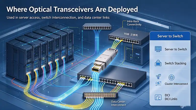
Data centers organize their networking into structured tiers. The most common design today is the spine-and-leaf architecture. Leaf switches connect directly to servers and storage. Spine switches connect the leaves to each other, forming a full-mesh fabric. Traffic between any two servers may traverse a leaf, a spine, and another leaf, often using equal-cost multipath routing to distribute load evenly.
Optical transceivers make this architecture feasible. In a spine-and-leaf fabric, leaf switches use fabric-facing transceivers to connect upward to every spine, while client-facing transceivers connect downward to servers. A single leaf switch may hold dozens of optical ports, and a large data center may deploy tens of thousands of transceivers across its fabric.
The alternative—copper cabling for every link—works only for very short distances at lower speeds. As speeds rise above 10 Gbps, copper's signal degradation over distance becomes prohibitive. Optical transmission suffers far less attenuation and is immune to electromagnetic interference, making it the only practical medium for the multi-meter and multi-kilometer runs that connect modern switching tiers.Why Data Centers Depend on Optical Transceivers
Several converging pressures explain why optical transceivers have become indispensable rather than merely useful.
Bandwidth density. A modern switch chip can drive 12.8 Tbps or more of aggregate throughput. Reaching that capacity through a fixed faceplate requires extremely dense port configurations. Pluggable optics allow network operators to populate ports incrementally, mixing speeds and reaches as needs dictate. An empty QSFP-DD port can later host a 400G or 800G module without replacing the switch.
Distance flexibility. Inside a single rack, a passive copper cable might suffice. Between rows or across a hall, active optical cables or individual transceivers with fiber patch cords carry the signal. Between buildings on a campus or across a metro region, coherent optical modules extend the reach to tens or hundreds of kilometers. The same switch port can serve any of these scenarios with the right transceiver installed.
Energy efficiency per bit. While an individual high-speed optical module consumes 10 to 20 watts or more, it moves vastly more data per unit of energy than copper alternatives at equivalent distances. Optical transmission also avoids the resistive heating losses that plague copper at high frequencies.
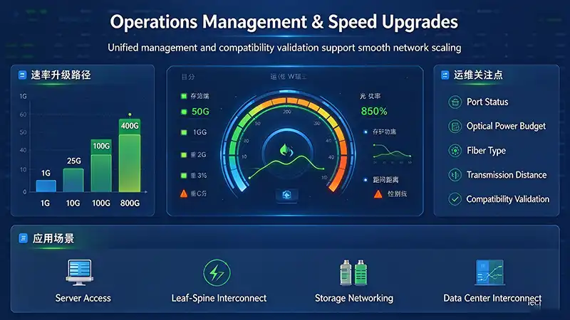
Standardization and operational simplicity. Pluggable modules follow published specifications for electrical interfaces, management interfaces, and optical characteristics. A technician can hot-swap a failed module without powering down the switch. Diagnostic data—temperature, laser bias current, receive optical power—flows through standardized management channels, enabling proactive maintenance.
How Transceivers Fit Into Spine-and-Leaf Fabrics
Consider a single leaf switch in a typical cloud data center. Its downlink ports, often SFP28 or QSFP28, connect to servers via short-reach optics or copper cables. Its uplink ports, frequently QSFP-DD or OSFP, connect to spine switches using 400G or 800G modules over parallel multimode fiber for short spans or single-mode fiber for longer runs.
Each spine switch mirrors this pattern at higher port counts. Every leaf connects to every spine, creating a non-blocking fabric where any server can reach any other server with predictable latency and bandwidth. The optical transceivers at each end of every link perform the electrical-to-optical conversion that makes this any-to-any connectivity possible.
The fabric-facing transceivers on leaf and spine switches often use parallel fiber connectivity. A 400G module might drive eight lanes of 50 Gbps each over eight fiber pairs, terminated in an MPO connector with 16 or 24 fibers. An 800G module doubles that lane count or increases per-lane speed to 100 Gbps, requiring MPO-16 or dual MPO-8 interfaces.
On the client side, breakout cables allow a single high-density switch port to serve multiple lower-speed devices. A 400G QSFP-DD port, for example, can split into four 100G links to four separate servers through a breakout cable. This flexibility lets operators match port economics to actual server connectivity needs without stranding capacity.
The Evolution of Speed: From 10G to 1.6T
Transceiver speeds have advanced relentlessly in response to compute and storage demands. Each generation brings new modulation techniques, packaging challenges, and thermal considerations.
The 10G era established SFP+ as the standard for server access. Simple non-return-to-zero (NRZ) modulation sent one bit per symbol per lane. Direct-attach copper cables handled distances up to a few meters; short-reach optics covered longer runs.
The 100G era introduced four-lane QSFP28 modules using 25 Gbps lanes. Some early implementations used 10 Gbps lanes in a 10x10 configuration, but 4x25 became dominant. Receiver equalization improved to compensate for channel impairments, and management interfaces matured to provide per-lane diagnostics.
The 400G era brought two architectural shifts. First, lane rates rose to 50 Gbps or 100 Gbps, requiring PAM4 modulation—a technique that encodes two bits per symbol across four signal levels, doubling spectral efficiency compared to NRZ. Second, lane counts increased to eight, creating denser electrical and optical interfaces. Power dissipation per module climbed, making thermal design a first-order concern in switch chassis.
The 800G generation, now entering widespread deployment, pushes both trends further. Modules use eight lanes of 100 Gbps or sixteen lanes of 50 Gbps. Advanced digital signal processing handles the greater signal integrity challenges. The highest-volume deployments cluster in AI training fabrics, where GPU-to-GPU communication demands enormous bandwidth over short distances.
The 1.6T horizon approaches as switch silicon reaches 51.2 Tbps capacity. Silicon photonics integration becomes essential at these rates, allowing tighter component placement and better power efficiency than discrete optical assemblies. Early 1.6T modules are expected to follow the eight-lane pattern with 200 Gbps per lane, relying on sophisticated modulation and forward error correction.
The Role of Modulation and Signal Processing
Moving more data through a single fiber or lane requires encoding more information into each signaling interval. The industry has largely transitioned from NRZ, which sends one bit per symbol, to PAM4, which sends two bits per symbol by using four amplitude levels.
PAM4 doubles throughput without doubling the symbol rate, but it reduces the signal-to-noise ratio margin by roughly a factor of three compared to NRZ. Compensating for this requires more powerful digital signal processors inside the module. These DSPs perform equalization, clock and data recovery, error correction, and sometimes gearbox functions that adapt lane counts between the electrical and optical domains.
At the highest speeds, particularly for longer-reach applications, coherent detection enters the picture. Coherent optics encode information in both the amplitude and phase of light, enabling far greater spectral efficiency and reach than direct-detect schemes. Coherent modules are more complex and power-hungry, so they see deployment primarily in data center interconnect scenarios spanning tens to hundreds of kilometers, where their advantages justify the cost.
For the shorter reaches that dominate intra-data-center traffic, direct-detect PAM4 remains the workhorse. It offers the best balance of cost, power, and complexity for links under a few kilometers.
Form Factors and Connector Ecosystem
The pluggable form factor ecosystem has evolved alongside speed requirements. Each generation balances density, thermal capacity, and backward compatibility.
QSFP-DD (Quad Small Form Factor Pluggable Double Density) doubles the electrical lanes of QSFP28 by adding a second row of contacts. It accepts existing QSFP modules, protecting investments in older optics. An 800G QSFP-DD module might use eight electrical lanes at 100 Gbps each, matching the lane count of the optical interface.
OSFP (Octal Small Form Factor Pluggable) uses a slightly larger package with integrated heat spreaders. The additional thermal headroom accommodates the higher power dissipation of 800G and future 1.6T modules. OSFP has gained particular traction in AI networking environments where dense GPU clusters generate intense heat loads.
Connector choices follow from the optical lane structure. Parallel single-mode or multimode links terminate in MPO (Multi-fiber Push-On) connectors with 8, 12, or 16 fibers. Duplex links using wavelength division multiplexing—where multiple wavelengths share a single fiber pair—terminate in standard LC connectors. The choice depends on reach, fiber plant, and cost priorities.
Optical Transceiver Form Factor Comparison
| Form Factor | Lanes | Typical Speeds | Common Reach | Primary Use Case |
|---|---|---|---|---|
| SFP | 1 | 1 Gbps | Up to 10 km | Legacy access, low-bandwidth links |
| SFP+ | 1 | 10 Gbps | Up to 10 km | Server access, older fabrics |
| SFP28 | 1 | 25 Gbps | Up to 10 km | Current server access ports |
| QSFP+ | 4 | 40 Gbps | Up to 10 km | Legacy aggregation |
| QSFP28 | 4 | 100 Gbps | Up to 10 km | Leaf-spine uplinks, server access |
| QSFP-DD | 8 | 400G / 800G | Up to 10 km (DR/FR) | High-density fabric, AI back-end |
| OSFP | 8 | 400G / 800G / 1.6T | Up to 10 km+ | AI clusters, high-power optics |
| Coherent ZR/ZR+ | 1-2 | 400G / 800G | 80 km to 1000+ km | Data center interconnect |
Key takeaway: Form factor selection follows port speed, thermal budget, and backward compatibility requirements. QSFP-DD preserves compatibility with older QSFP modules, while OSFP prioritizes thermal headroom for the highest-power optics.
Active Optical Cables and Direct Attach Copper
Not every optical connection uses separate transceivers and patch cords. Active Optical Cables (AOCs) embed transceiver circuitry permanently inside a cable assembly, presenting electrical interfaces at both ends. AOCs cost less than two discrete transceivers plus fiber, and they eliminate the need for connector cleaning and patch cord management. They dominate mid-range reaches where permanent point-to-point links make sense.
Direct Attach Copper (DAC) cables go further, using copper conductors for very short runs within or between adjacent racks. Passive DACs consume essentially no power and add negligible latency. They work well up to a few meters at lower speeds but become impractical beyond that as signal degradation accelerates. Active copper cables with embedded signal conditioning extend the reach somewhat but remain a short-distance solution.
AOCs and DACs simplify deployment, but they lack the flexibility of true pluggable optics. A damaged cable requires replacing the entire assembly. Changing the link speed means replacing the cable rather than swapping a module. For the structured, long-lived links that dominate spine-and-leaf fabrics, pluggable transceivers plus fiber remain the preferred approach.
Power and Thermal Considerations
Power consumption has become a defining constraint. An 800G optical module may dissipate 14 to 20 watts or more. Multiply that by the hundreds or thousands of ports in a large switch, and the thermal load rivals that of the switching silicon itself.
This power draw stems from several sources: laser drive circuitry, DSP equalization, thermal tuning of laser wavelengths, and the inherent inefficiency of converting between electrical and optical domains. Each generation has improved efficiency per bit, but absolute power per module has risen because port speeds have grown faster than efficiency gains.
Thermal management strategies include:
Heat spreaders and finned cages that conduct heat away from the module and into the chassis airflow.
Temperature monitoring through standardized management interfaces, allowing operators to detect overheating before it causes link failures.
Airflow design that directs cool air across the faceplate where modules sit, rather than pulling preheated air from the switch interior.
Power over Ethernet ports on the faceplate exacerbate the challenge by adding heat sources in close proximity to sensitive optics. Careful thermal simulation and validation testing are essential when deploying high-density optical ports.
Monitoring, Diagnostics, and Management
Pluggable transceivers expose a wealth of diagnostic data through standardized management interfaces. Digital Optical Monitoring (DOM) reports:
Transmit and receive optical power
Laser bias current
Module temperature
Supply voltage
Per-lane error counters
This telemetry flows to network management systems, enabling operators to track link health, predict failures, and troubleshoot issues without physically inspecting connections. A gradual decline in receive optical power might indicate connector contamination or fiber damage. Rising laser bias current can signal an aging laser approaching end of life.
The management interface itself is defined by industry specifications. SFP modules use the two-wire management protocol defined in SFF-8472. QSFP and QSFP-DD modules use the SFF-8636 and Common Management Interface Specification (CMIS), respectively. These standards ensure that a management system can interrogate transceivers from any vendor that complies with the relevant specification.
Where Transceivers Go Next: Co-Packaged Optics and Silicon Photonics
The pluggable transceiver model, successful for decades, now faces pressure from the very speeds it enabled. At 1.6T and beyond, the electrical path from switch silicon to faceplate becomes a significant source of signal loss and power consumption. Driving high-speed signals across printed circuit board traces requires increasing amounts of equalization, which itself consumes power and adds latency.
Co-packaged optics (CPO) addresses this by moving the optical engine inside the switch package, directly alongside the switching ASIC. Electrical signals travel millimeters instead of centimeters, dramatically reducing the drive power required. The optical engine connects to external fiber through a detachable connector on the package perimeter.
CPO promises substantial power savings—potentially 30 to 40 percent compared to pluggable modules at equivalent speeds—and much higher port density. The technology relies on silicon photonics, which fabricates optical components using CMOS-compatible processes, enabling tight integration of modulators, waveguides, and photodetectors on a single chip.
Challenges remain. CPO shifts the optical interface from a replaceable module to a soldered assembly. A single optical engine failure could require replacing an entire switch package rather than a pluggable module. Manufacturing yield for multi-engine CPO assemblies remains a concern; with 32 optical engines at 95% individual yield, overall system yield drops below 20%. Repair and upgrade paths are less flexible than the pluggable model that network operators have relied on for twenty years.
Silicon photonics is not waiting for CPO to mature. It already appears in a large fraction of 400G and 800G pluggable modules, particularly those using wavelength division multiplexing or requiring high levels of integration. As speeds rise, silicon photonics integration within pluggable form factors will continue to grow, offering better performance and manufacturability even before co-packaging becomes mainstream.
Data Center Interconnect: Extending the Fabric
Optical transceivers also play a critical role connecting separate data center facilities. Data Center Interconnect (DCI) links span campuses, metro regions, and sometimes longer distances, enabling workload distribution, disaster recovery, and resource pooling across sites.
Coherent optical modules designed for DCI operate over single-mode fiber at distances from 80 kilometers to several thousand kilometers. The ZR and ZR+ pluggable standards bring coherent technology into the same pluggable form factors used inside data centers, allowing routers and switches to terminate DCI links directly without separate transport equipment.
This IP-over-optical integration simplifies network architecture and reduces cost. A router can now host a 400G ZR+ module that communicates directly with a counterpart hundreds of kilometers away, eliminating an entire layer of optical transport gear. As coherent pluggables reach 800G and eventually 1.6T, this convergence will deepen.
Selecting the Right Transceiver for the Application
Choosing among the many available transceiver types requires matching several parameters to the deployment scenario.
Reach is the first filter. Within a rack, DAC or short-reach multimode optics suffice. Between rows, multimode or single-mode short-reach modules cover the distance. Across a campus or metro area, single-mode with wavelength division multiplexing or coherent optics becomes necessary. Each reach class has standardized optical specifications—SR, DR, FR, LR, ER, ZR—that define the power budget, wavelength, and fiber type.
Speed follows from switch port capabilities and server NIC speeds. It rarely makes sense to deploy optics faster than the endpoints can drive, though spare capacity may be justified for future upgrades.
Fiber plant compatibility is a frequent oversight. Multimode fiber installed for 10G or 40G may not support 400G or 800G over the expected distances. OM3 fiber, once common, has limited bandwidth for higher-speed parallel transmission. OM4 and OM5 provide better performance but still impose distance limits.
Power and thermal budget must be verified before deployment. A switch rated for a certain number of ports at a specific transceiver power class may require reduced port density or enhanced cooling if higher-power modules are installed.
Vendor compatibility matters more than the multi-source agreements suggest. While standards ensure basic interoperability, real-world behavior can vary. Switch vendors publish compatibility lists, and testing modules in representative configurations before wide deployment remains a prudent practice.
Frequently Asked Questions
What is the difference between an optical transceiver and an optical module?
The terms are often used interchangeably. "Optical transceiver" emphasizes the device's dual transmit-and-receive function. "Optical module" is a broader term that can include transmitters, receivers, and transceivers. In data center contexts, both refer to the same pluggable component that converts electrical signals to optical signals and back.
Why are optical transceivers preferred over copper cables in data centers?
Optical transceivers support far greater distances without signal degradation, carry more bandwidth per lane, resist electromagnetic interference, and consume less energy per bit at high speeds. Copper remains practical only for very short runs, typically within a rack or between adjacent racks.
How long do optical transceivers last in a data center?
Most modules are designed for five to ten years of continuous operation. Actual lifespan depends on temperature, humidity, laser aging, and handling practices. Digital Optical Monitoring data—particularly laser bias current and receive power—helps predict degradation before a link fails.
Can I mix transceivers from different vendors in the same switch?
Multi-source agreements ensure basic interoperability, and in most cases modules from different vendors will link successfully. However, real-world performance can vary. Checking the switch vendor's compatibility list and testing representative configurations before wide deployment is a sound practice.
What is the difference between SR, DR, FR, LR, and ER optics?
These designations describe reach and fiber type. SR (Short Reach) works over multimode fiber up to about 100 meters. DR (500 meters) and FR (2 kilometers) use single-mode fiber for moderate distances. LR (10 kilometers) and ER (40 kilometers) extend further over single-mode fiber. ZR and ZR+ coherent modules reach 80 kilometers and beyond.
What happens if I plug a lower-speed transceiver into a higher-speed port?
Most high-speed ports negotiate down to the module's speed, provided the form factor is compatible. A QSFP-DD port can accept a QSFP28 module at 100G, for example. However, the port cannot operate faster than the installed module, and some port features may be unavailable at lower speeds.
Are optical transceivers hot-swappable?
Yes. Standard pluggable modules are designed for hot-swap operation, meaning they can be inserted or removed without powering down the switch. This capability is central to the operational simplicity of the pluggable model and allows rapid replacement of failed modules.
What is the difference between an optical transceiver and an active optical cable?
An active optical cable embeds transceiver circuitry permanently inside the cable assembly, presenting electrical interfaces at both ends. A standalone transceiver plugs into a port and mates with separate fiber patch cords. AOCs cost less for fixed point-to-point links; pluggable transceivers offer greater flexibility for structured cabling and future upgrades.
The Broader Impact on Data Center Design
Optical transceivers shape data center architecture in ways that extend beyond the link level. The availability of high-bandwidth, low-latency optical connectivity enables disaggregated designs, where compute, storage, and memory resources pool independently and connect through a high-speed fabric rather than residing in the same chassis.
AI and machine learning workloads intensify these demands. Training a large language model requires thousands of GPUs to exchange gradients and activations continuously. The network fabric carrying this traffic must provide extremely high bandwidth with predictable latency. Optical transceivers—particularly 800G and future 1.6T modules—form the physical layer of these AI back-end networks.
The power and cost of this optical infrastructure, once a minor line item, now ranks alongside compute and cooling as a primary planning constraint. Data center operators track transceiver shipments as a leading indicator of AI infrastructure buildout. The optical interconnect has become, in effect, the circulatory system of the modern data center—unseen by users, but absolutely essential to every operation.
Optical transceivers transform electrical impulses into light and back again, bridging the gap between the confined world of semiconductor chips and the long-distance reach of fiber optic cabling. They appear in every link of the spine-and-leaf fabric, every server access connection, every inter-building span, and increasingly in the co-packaged engines that drive AI training clusters.
Their evolution from simple 1 Gbps modules to 800G and 1.6T devices mirrors the broader trajectory of data center computing: relentless increases in density, speed, and efficiency, driven by demands that seemed unimaginable a decade ago. Understanding how these modules function, where they fit, and what distinguishes one type from another equips infrastructure professionals to make sound decisions about the networks they build and operate.
The optical transceiver is not merely a component. It is the enabling technology that allows thousands of independent computing systems to function as a cohesive, high-performance whole.