
Product Overview
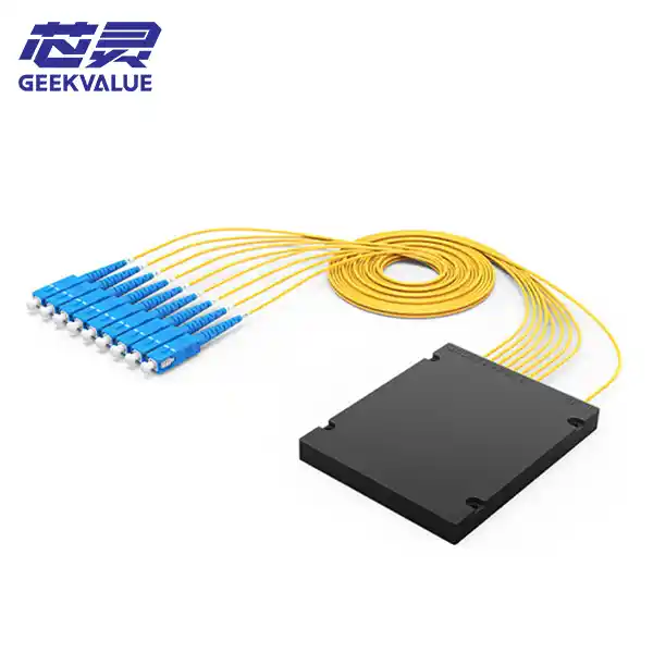
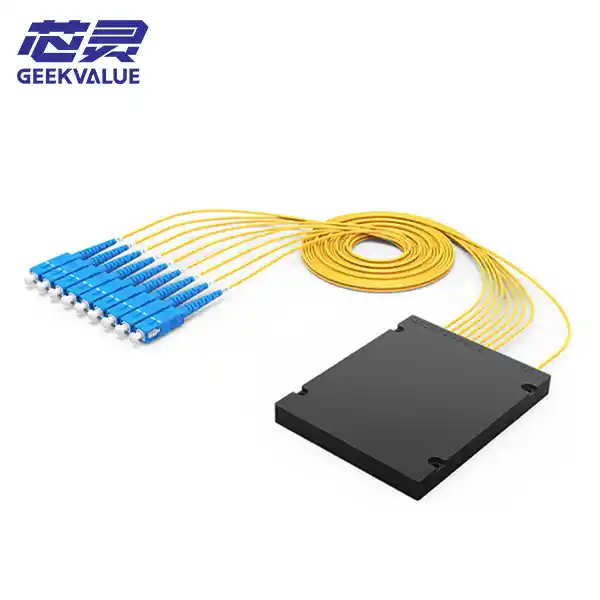 A PLC splitter, short for Planar Lightwave Circuit Splitter, is a core passive device in fiber optic links.
Its core function is to proportionally (usually uniformly) split a single input optical signal into multiple output signals. You can think of it as an "optical signal distributor" in a fiber optic network. In Passive Optical Networks (PON) and Fiber to the Home (FTTH) scenarios, it allows multiple users to share a single backbone fiber interface, which is crucial for reducing network construction costs.
Working Principle and Structure: PLC splitters are manufactured based on Planar Lightwave Circuit (PLC) technology. Its core is an optical waveguide chip fabricated on a quartz substrate using semiconductor processes (photolithography, etching, etc.).
Core Principle: The chip contains multiple Y-shaped branch structures. When an optical signal passes through, the optical power is evenly split in two at each branch point. By cascading multiple Y branches, 1×4, 1×8, up to 1×64, or even 1×128 splitting can be achieved.
Basic Components: A complete PLC splitter mainly consists of two parts:
* **Optical Waveguide Chip:** The core component enabling optical splitting.
* **Fiber Optic Array (V-groove):** Precisely arranged at both ends of the chip, used to connect the input and output optical fibers.
Main Classifications:** PLC splitters are mainly classified as follows:
* **By Port Structure:**
* **1×N Type:** 1 input port, N output ports.
* **2×N Type:** 2 input ports (often used for redundancy), N output ports.
* **Common Splitting Ratios:** 1:8, 1:16, 1:32, 1:64, etc.
* **By Packaging:** PLC splitters offer a variety of packaging options to adapt to different installation environments.
* **Bare Fiber/Miniature Type:** The smallest in size, often packaged inside larger equipment or instruments.
* **ABS Box Type:** One of the most common types, with a protective housing, suitable for various outdoor or indoor environments.
* **Plug-in Type:** A pluggable design for flexible configuration and replacement on optical distribution frames.
Rack-mount: Installed in a standard 19-inch communication rack, used in centralized management scenarios such as computer rooms.
Key Performance Indicators
The performance of a PLC splitter is mainly evaluated based on the following parameters:
Insertion Loss: The energy lost by the optical signal after passing through the splitter; a lower value is better. The more splits, the greater the loss. For example, the loss of a 1×8 splitter is typically ≤10.5dB, while the loss of a 1×32 splitter may reach ≤16.5dB.
Return Loss: The energy reflected back to the light source by the splitter; a higher value is better, typically requiring ≥50dB.
Uniformity: Measures the consistency of optical power across all output ports; a lower value indicates more uniform beam splitting.
Polarization Dependent Loss (PDL): The loss caused by changes in the polarization state of the optical signal; typically requiring ≤0.2dB.
Operating Wavelength: Typically covers a wide wavelength range from 1260nm to 1650nm, and the splitting ratio remains stable across this wide wavelength range.
Application Scenarios
PLC splitters are the cornerstone of modern fiber optic networks and have extremely wide applications.
Fiber to the Home (FTTH/FTTX): Distributes a single backbone optical signal to dozens or even hundreds of home users between the operator's central office and the user's building.
Optical Network (PON): In EPON, GPON, and other systems, it serves as a core device connecting the Optical Line Terminal (OLT) and Optical Network Unit (ONU).
Cable Television (CATV): Used to distribute television signals from the central equipment room to various optical nodes.
Data Centers and Local Area Networks (LANs): Used for optical signal distribution and aggregation within cabinets or between devices.
Relevant Standards
The production and inspection of PLC splitters mainly follow the following standards:
Chinese Telecommunications Industry Standard: YD/T 2000.1 series.
International Reliability Standards: Telcordia GR-1209-CORE and GR-1221-CORE.
Environmental Standards: Compliant with RoHS requirements.
PLC vs. FBT: How to Choose?
Besides PLC splitters, another common type on the market is the fused biconical taper (FBT) splitter. A comparison of the two is as follows:
Comparison Dimensions:
PLC Splitter (Planar Waveguide)
FBT Splitter (Fused Biconical Taper)
Technical Principle: Semiconductor process to fabricate optical waveguide chips; multiple optical fibers are fused and tapered together.
Split Uniformity: Excellent, good consistency in loss across channels; average, uniformity decreases with increasing number of channels.
Wave Sensitivity: Low, stable performance over a wide wavelength range; high, splitting ratio varies significantly with wavelength.
Multi-Channel Cost: Low, advantages become more pronounced with more channels; high, complex manufacturing, low yield.
Reliability: High, compliant with Telcordia standards; average.
Applicable Scenarios: FTTH/PON and other scenarios requiring multiple splits; few splits (e.g., 1×2, 1×4) or scenarios extremely sensitive to cost.
Summary: In conclusion, PLC splitters are an indispensable core component in modern fiber optic networks, especially FTTH and PON networks. With its superior performance, high reliability, and cost advantage in multi-channel applications, it has become the mainstream choice for optical signal distribution.