Product Overview
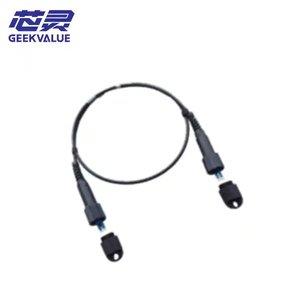
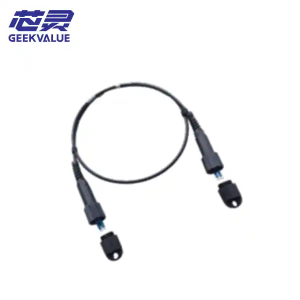 A fiber optic connector is a core passive component used to establish detachable and repeatable connections between optical fibers. Its function is to precisely align the end faces of two fibers, ensuring that optical signals pass through with minimal loss.
You can think of a fiber optic connector as a "smart plug" for optical fiber; it works in conjunction with a "socket" (the fiber optic adapter)—which handles securing and mating—to form a complete fiber optic connection solution.
Core Structure and Working Principle
Fiber optic connectors feature a precision internal structure, primarily composed of the following components:
Ferrule: The core component. Typically made of high-precision zirconia ceramic, it features a micro-hole (approximately 125 μm in diameter) in the center to precisely house the optical fiber.
Connector Body: The housing that secures the ferrule and provides protection.
Cable: The section of optical fiber to be connected.
Coupling Mechanism: The structure used to secure and lock the connector onto the adapter.
The working principle is as follows: when two connectors are mated via an adapter, an internal ceramic sleeve precisely aligns the two ferrules. Since the core diameter of single-mode fiber is only 8–10 μm, even the slightest misalignment can result in signal loss; therefore, the precision required for this alignment is extremely high.
How are they classified?
There is a wide variety of fiber optic connectors, which can be classified according to the following criteria:
Classification by interface structure (most common): Connectors with different structures vary in appearance and locking mechanisms.
Type Characteristics Typical Applications
LC (Lucent Connector) Compact square design, plug-and-play; ferrule size is only 1.25 mm. Data centers (holding nearly 60% market share), high-density cabling, SFP optical modules.
SC (Subscriber Connector) Standard square design, plug-and-play; push-pull locking mechanism; easy to operate. Enterprise networks, FTTH (Fiber to the Home), GPON networks.
FC (Ferrule Connector) Circular metal threaded connection; highly secure and vibration-resistant. Telecom backbone networks, long-distance single-mode transmission, test instruments. ST (Straight Tip) Round bayonet-style connector; locks by inserting and twisting a half-turn. Used in early multimode networks (such as campus networks and surveillance systems); currently being phased out.
MPO/MTP Multi-fiber, high-density connector capable of connecting 12, 24, or even more fibers simultaneously. Suitable for 40G/100G/400G high-speed data centers and high-density backbone cabling.
Classification by end-face polish (affects signal reflection): Refers to the polished shape of the ferrule end-face, which directly impacts return loss.
Type Characteristics Typical Return Loss Typical Applications
PC (Physical Contact) Spherical polish; basic physical contact. ≥45 dB Standard short-range communication
UPC (Ultra Physical Contact) Optimized version of PC; superior surface finish. ≥50 dB High-speed Ethernet, FTTH (Fiber to the Home)
APC (Angled Physical Contact) 8° angled polish; excellent return loss performance. ≥60 dB CATV (Cable TV), high-precision fiber optic sensing
Important Note: PC, UPC, and APC end-faces differ and are not intermateable; forced mating will severely degrade connection performance.
Classification by transmission mode:
Singlemode connector: Compatible with 9/125 μm fiber; used for long-distance, high-speed transmission.
Multimode connector: Compatible with 50/125 μm or 62.5/125 μm fiber; used for short-range transmission, such as within data centers.
Key Performance Indicators
Fiber optic connector performance is primarily evaluated using the following parameters:
Insertion Loss (IL): The amount of optical signal energy lost when passing through the connector. Lower values are better; typically ≤0.5 dB is required, while high-quality products can achieve ≤0.3 dB.
Return Loss (RL): The amount of energy reflected back to the light source from the connector end-face. Higher values are better; APC connectors typically offer the best return loss performance.
Repeatability: The ability to maintain performance (such as insertion loss) after multiple mating/unmating cycles. Durability: The number of mating cycles a connector can withstand; standards typically require ≥1,000 cycles. Application Scenarios
Fiber optic connectors are fundamental to the construction of various fiber optic networks and have a wide range of applications. Telecommunications networks: Used in scenarios requiring high stability, such as base stations and backbone networks.
Data centers: Widely utilize LC and MPO connectors to achieve high-density, high-speed interconnects.
Fiber to the Home (FTTH): Connectors such as the SC type are used at the subscriber end and at splitters.
Cable TV (CATV): Connectors with APC end-faces are typically used due to strict signal quality requirements.
Testing Instruments: Used in conjunction with light sources, optical power meters, and other equipment to test fiber optic links.
Selection and Maintenance
Key Selection Criteria:
Match Interface Type: Confirm whether the device port is SC, LC, or another type.
Match Fiber Mode: Confirm whether single-mode or multi-mode fiber is being used.
Match End-face Type: Select PC/UPC or APC based on the application scenario.
Consider Ferrule Material: Prioritize zirconia ceramic ferrules for high precision and wear resistance.
Cleaning and Maintenance:
Fiber optic connectors are extremely sensitive to contamination; dust and oil can significantly increase insertion loss. Regular cleaning with specialized tools (such as cleaning pens or swabs) is recommended. Exercise caution during the process to avoid scratching the end-face.
Summary
In summary, fiber optic connectors serve as crucial "bridges" for flexible connectivity and management within optical networks. Although small, their performance directly determines the transmission quality of the entire fiber optic link. Selecting the right, high-quality connectors and maintaining them properly are the foundations for building high-speed, stable fiber optic networks.