
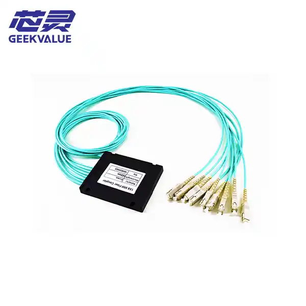
Product Overview
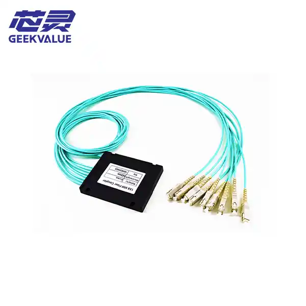 Fused Biconical Transistor (FBT) splitters are mature passive optical devices used in optical communication networks. Their core function is similar to PLC splitters: splitting a single optical signal into multiple optical signals. You can think of them as optical signal distributors manufactured using the traditional "fusion splicing and stretching" process, a technology with over twenty years of history and experience.
Working Principle: The Wisdom of Traditional Technology
The manufacturing process of an FBT splitter can be imagined as a very precise "candy-stretching" process:
Fiber Preparation: Removing the cladding layers of two or more optical fibers.
Fuse Splicing and Stretching: Placing bare optical fibers side-by-side and heating them at high temperatures to melt them while simultaneously stretching them outwards.
Real-time Monitoring: During the stretching process, the equipment monitors the changes in the splitting ratio in real time. Stretching ends when the splitting ratio reaches the set value.
Device Formation: After stretching, a special waveguide structure resembling a "double cone" is formed in the heated area. One end retains one fiber as the input, and the other end serves as multiple outputs.
Key Features: Advantages and Limitations
Core Advantages:
* Low Cost: FBT splitters utilize mature manufacturing processes, resulting in low-cost raw materials (quartz substrates, optical fibers, steel pipes, etc.). This cost advantage is particularly significant for low-channel-count splitters such as 1×2 and 1×4.
* Flexible Splitting Ratio: Non-uniform splitters can be manufactured, allowing for flexible adjustment of the splitting ratio (e.g., 20:80, 40:60) to meet the optical power distribution requirements of different lines.
* Low Additional Loss: High-quality products can achieve additional losses as low as ≤0.2dB.
Key Limitations:
* Wavelength Sensitivity: FBT splitter losses are highly sensitive to optical wavelength, typically requiring selection based on specific operating wavelengths (e.g., 1310nm, 1550nm). This is a critical drawback in multi-wavelength fusion network scenarios.
* Poor Uniformity: For uniform splitters, the output optical power consistency is inferior to that of PLC splitters. The maximum loss difference for a 1×4 splitter is approximately 1.5 dB, while the loss difference is even greater for 1×8 and higher splitters. Insufficient temperature stability: Insertion loss fluctuates significantly with temperature changes.
Larger size for multi-channel splitters: Mature processes can only produce 1×4 splitters at a time. Higher channel counts (e.g., 1×8, 1×16) require multiple 1×2 splitters in parallel, leading to increased size.
Key performance indicators: When evaluating FBT splitter performance, the following core parameters should be considered:
Insertion loss (IL): The energy lost by the optical signal after passing through the splitter; lower values are better.
Return loss (RL): The energy of the optical signal reflected back to the light source by the splitter; higher values are better.
Additional loss: The extra loss caused by the splitter itself; lower values are better.
Uniformity: Measures the consistency of optical power at the output ports; lower values indicate more uniform splitting.
Polarization-dependent loss (PDL): Loss caused by changes in the polarization state of an optical signal; typically required to be ≤0.2dB.
Typical Application Scenarios
Due to its cost advantage, FBT splitters still have wide applications in certain specific scenarios:
Small-scale splitting: Used for low-channel-count splitting in Fiber to the Home (FTTH/FTTX) scenarios, such as 1×2 or 1×4 splitting.
Cable TV networks (CATV): Used for optical power distribution of television signals.
Monitoring systems: Used in scenarios requiring the distribution of optical signals to multiple monitoring points.
Test equipment: As an optical power distribution device in optical communication test instruments.
FBT vs. PLC: Comparison Table
Size Comparison: FBT Splitter (Fused Tapered Fiber) PLC Splitter (Planar Waveguide)
Technical Principle: Fused and stretched optical fiber forms a biconical waveguide; waveguide chips are manufactured using semiconductor processes.
Cost: Low, especially below 1×4; High, but the cost advantage becomes more obvious with more channels.
Operating Wavelength: Only supports specific wavelengths (e.g., 1310/1550nm); Full band support (1260~1650nm).
Split Uniformity: Poor; uniformity is amplified after cascading; Excellent; good consistency of loss across channels.
Temperature Stability: Poor; loss fluctuates greatly with temperature; Excellent; wide and stable temperature range.
Multi-channel Size: Large; cascading of multiple components leads to increased size; Small; high integration; compact size.
Split Ratio Flexibility: High; can be made into non-uniform splitting; Fixed; mainly uniform splitting.
Relevant Standards: The production and inspection of FBT splitters mainly follow the following standards:
International Standards: Telcordia GR-1209-CORE and GR-1221-CORE.
Chinese Telecommunications Industry Standards: YD/T 2000.1 series. An earlier industry standard was YD/T 893-1997, "Technical Conditions for Fiber Optic Couplers."
Environmental Standard: Compliant with RoHS requirements.
Summary: In conclusion, FBT splitters are a mature, low-cost "traditional" optical splitter technology. Its advantages lie in low cost and flexible splitting ratios, while its disadvantages include wavelength sensitivity, poor uniformity, and relatively poor temperature stability.
In modern high-density, multi-wavelength fiber optic networks (such as FTTH), PLC splitters are gradually becoming mainstream. However, for small-scale splitting (below 1×4), extremely cost-sensitive projects, or specific scenarios requiring non-uniform splitting, FBT splitters remain an economical and practical choice.